Concept and system design
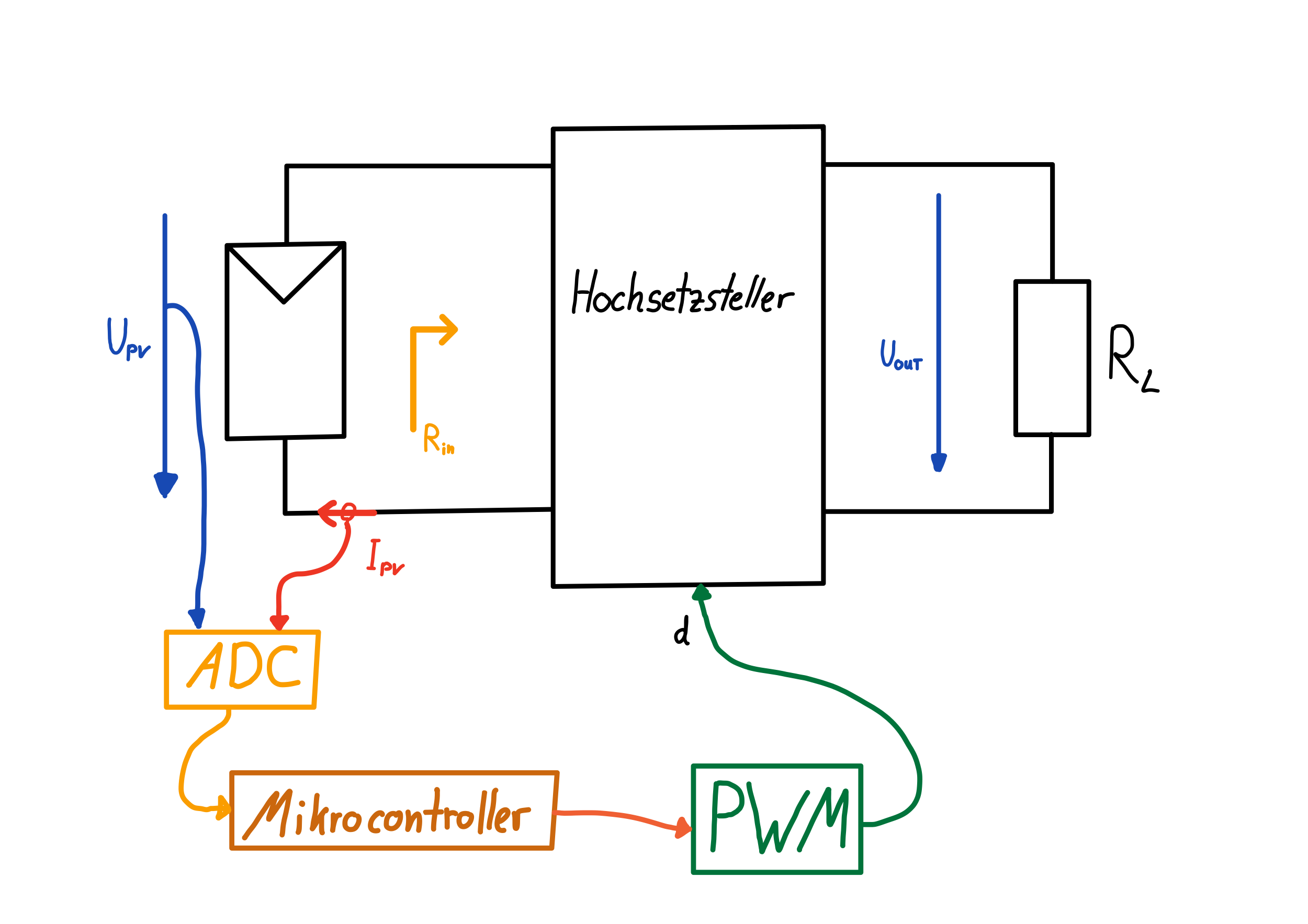
With the knowledge of the previous chapters, the concept of maximum power point tracking can now be demonstrated. As a rule, the resistance $R_{L}$ of the load connected to the PV module is not freely selectable and no power adjustment can be operated. The problem can be solved if the boost converter is connected between the PV module and the load. The concept shows this circuit and illustrates how the input resistance can be changed by adjusting the duty cycle. The step-up converter is shown as a block in this illustration; other DC/DC converters can also be used here.
Concept
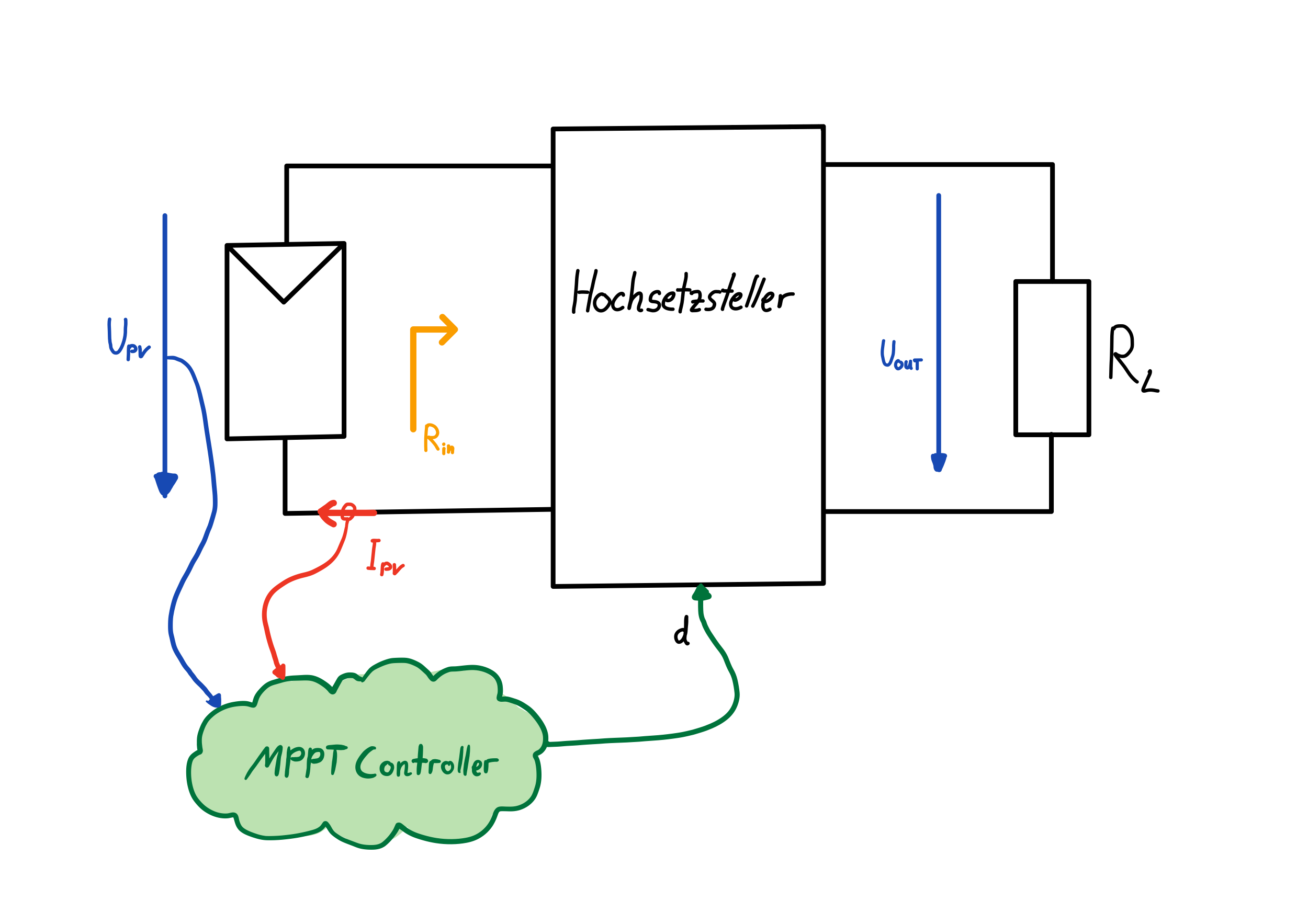
The MPPT method is realised with an MPPT controller. This requires information about the PV module to calculate the duty cycle $d$. The currently applied voltage $V_{pv}$ and the currently flowing current $I_{pv}$ are provided via corresponding measuring units. With this information, an algorithm can find the MPPT and set the corresponding duty cycle $d$ at the boost converter. The duty cycle indirectly influences the input resistance of the converter, so it can be optimally adjusted to the PV module with the help of the line matching. There are different methods to find the MPPT, in chapter mppt algorithms we will go into more detail about the algorithms discussed in this thesis.
For the practical implementation, a system is to be designed from the preceding considerations. For this purpose, the requirements for the system are first defined and the various components of the system are described. The aim is to gain a complete understanding of the system and to document the design decisions made during development. The solar module optimiser is to be operated on the input side with a solar module with the following properties:
-
Power: $P_{mpp}$ = 80W
-
Open circuit voltage: $V_{oc}$ = 24V
-
Short circuit current $I_{sc}$ = 5A
The power to be transmitted is assumed to be $P=100W$, but the module optimiser is designed with a maximum current of up to $I=10A$. The reason for this is to provide enough leeway for a possible overload. The voltage at the output shall cover a range between $15V<V_{out}<50V$ to be compatible with different loads. The MPPT controller is to be realised with a programmable microcontroller, which drives the boost converter on its output side with a PWM. As a peripheral, the controller already has a PWM module built in, this generates the required switching signal to control the Mosfet and thus also modulate the duty cycle $d$. On the input side, two pieces of information about the solar module are needed, the current voltage $V_{pv}$ and the current $I_{pv}$. The microcontroller is equipped with an ADC, which is to be used for the acquisition of this information. The voltages are to be made compatible with the measurable range of the ADC via voltage dividers. The current is to be measured via a Hall-effect sensor chip, which outputs an analogue voltage that can also be measured with the ADC. The MPPT controller either directly sets the duty cycle $d$ for the PWM of the boost converter at its output or it outputs a reference voltage $vRef$, this reference voltage is then passed on to a PI controller which regulates the output voltage $V_{out}$ and tries to regulate to the reference voltage $vRef$ with the manipulated variable $d$ i.e. the duty cycle of the boost converter. The implementation will show which method works more reliably.